Designing Float
Rigging
For
a
Rans S7
(or
any other aircraft)
2014/08/22
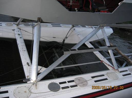
There is a wide variation in the design
of fittings for attaching floats to an aircraft. I believe that there are a few
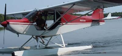
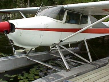
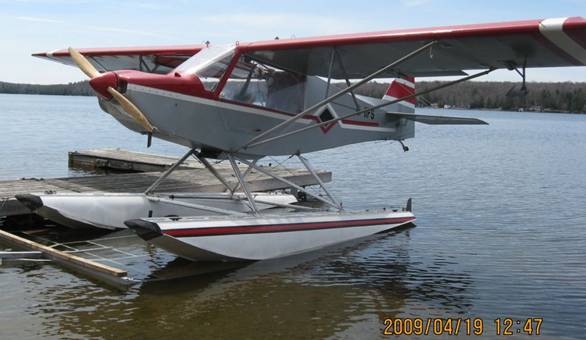
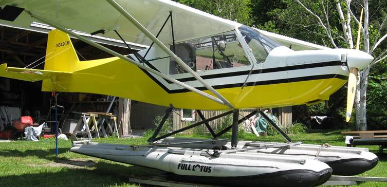
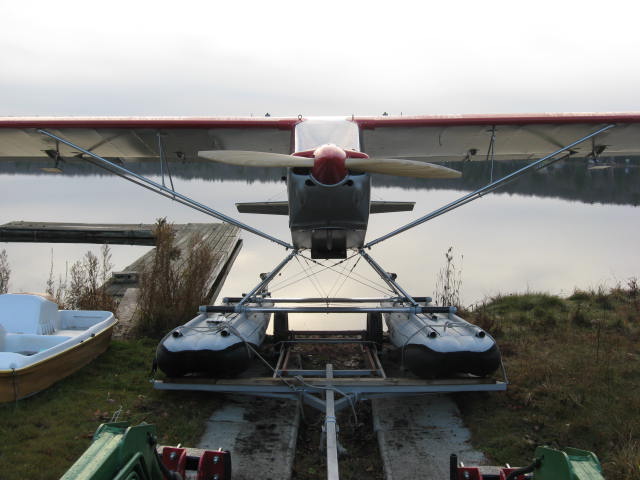
important rules to follow to achieve well designed rigging. While the S7 above is a very pretty aircraft
on Aerocet amphibs with rigging that works just fine, the design of the various
components can be improved.
A separate issue is the geometry of the
floats relative to the aircraft which will be addressed separately. See Geometry .
With three different sets of floats to
try in the spring of 2009, I needed a flexible rigging design. I wanted to get
away from fittings that are built with fixed angles.
For example, this is a welded top forward
fuselage fitting that was on one of my Rans S7 aircraft on Full Lotus floats.
This one had the Cub style gear.
This type of fitting pretty much fixes
the fuselage-to-float geometry. So, for example, you would not be able to
shorten or lengthen the rear strut to change the angle of the floats to the
plane without changing this bracket. Also producing it would require either a
very accurate fixture or tack welding it right on the plane which would be positioned
over the floats.
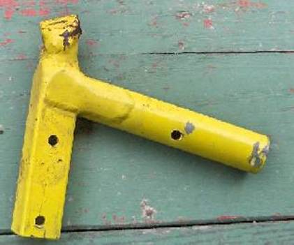
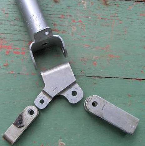
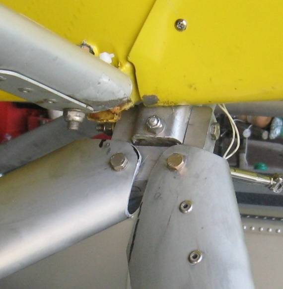
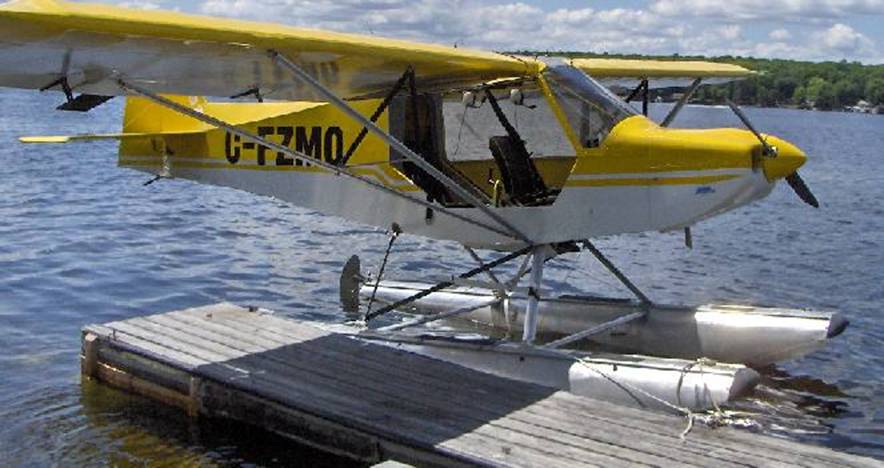
Here is a top rear fitting off the S7 on
the Aerocet amphib floats above:
It clamps to the vertical tube and is
bolted through the bushing Rans welds to all S7 airframes.
It does allow pivoting in a fore/aft
plane but again demands one specific float width/height combination because of
the welded tab. These floats also used a fixed tab on the floats to attach
front and rear struts so, again, no variation in angles allowed.
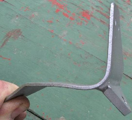
This is the top forward fitting on that
same Aerocet installation shown above. This design is reasonably good in that
pivoting is allowed in fore/aft angle of struts and float width but it requires
three machined parts, the formed “U” and a weld.
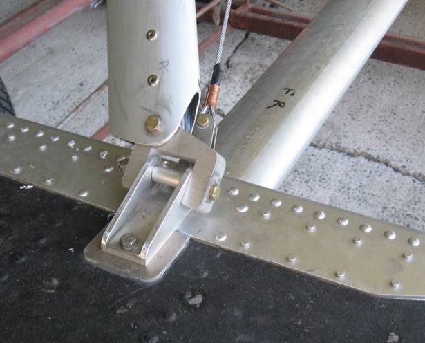
The lower strut to float fittings are
related to what the float manufacturer provides on the floats. On these 1941

The top front “porkchop” stub gear used by
Cessna, allowed some for/aft pivoting but fixed the float width/height.
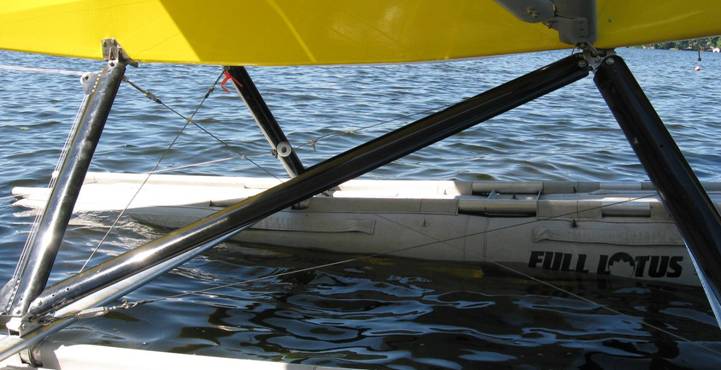
In the Aerocet case above, the streamline
tubing used for strut material has an inner cross section that allows for 1”
square material to be inserted but the inserted fittings must stay parallel to
the length of the strut. This material is the equivalent of Rans wing strut
tubing.
Many builders then used Rans 1” square
clevises to connect strut to brackets like this:
The diagonal strut takes ¾” material
While the requisite pivoting is achieved,
it does require the clevis because the strut cross section does not allow any
angular difference between strut and inner 1” material.
There are two ways around allowing an
angular difference between strut and fitting. One is to design a different
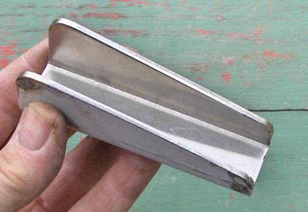
strut cross section. The other is to do away with the 1” clevis.
This material shown below the Rans strut
material, does allow the strut to mate to a bracket at a wide angular
range. The material at the top of the
picture was used on the Aerocet above
and is the same as Rans wing strut tubing; the bottom material is the other
style. Note the thicker centre section which not only adds considerable
strength but allows some pivoting. Its disadvantage is additional weight.
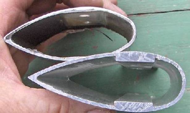
The top tubing is 1” inside; the bottom
¾.
For weight saving we want to use ¾” block
material. The bottom tube style will
bolt directly to the ¾ blocks; the upper tube requires filler at the block.
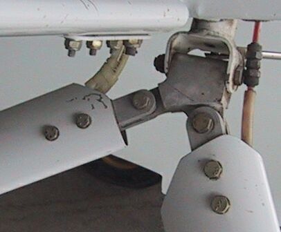
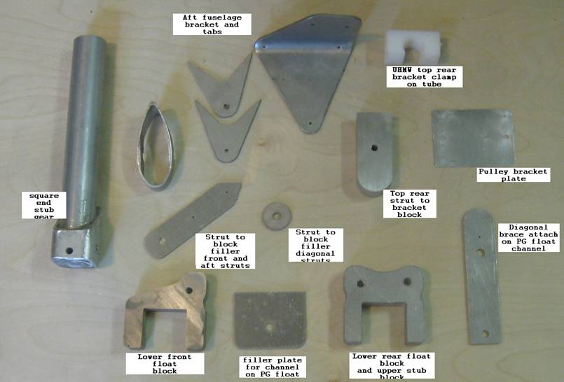
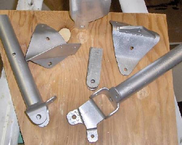
Here are the various parts that then go
together to make up the rigging:
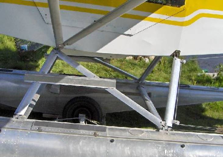
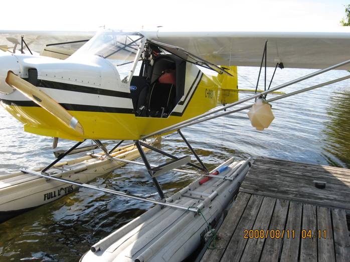
Here is the top front setup on my S7 on
Murphy 1500:
And the lower front block on PG floats:
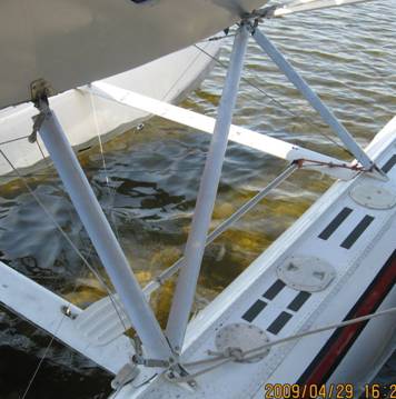
Below is the aft lower attachment
And finally top rear bracket and block:
This is made from 304 stainless and tig welded.
The jig shown further down is helpful here to enable tacking the tabs to the
bracket with fittings in place to guarantee the strut bolt is parallel to the
centre line of the fuselage. All the fingerprints are from the anti seize
compound I use.
IMPORTANT POINT Concerning water rudder steering:
With the pull/pull cable
system that most of us use for linking the water rudders to the air rudder,
make sure that the steering bar (distance between the cables) at the water
rudder is close to the length of the bar on the air rudder. For example, on the
Rans S7 the air rudder cables are about 6 ¼” apart. On the murphy floats, the
water rudder bar is only about 4”. This will cause a tightening of the cables
at full travel and can restrict movement and add stress to the rudder cables.
The steps are 2”
x 2” x 1/8 alum angle sitting on triangular blocks with a ¼” thru bolt which
goes through the strut material away from the center thick section.
To use the same type of attachment on
Full Lotus floats we have made up stainless steel channels that will bolt to
streamline spreader bars (and have unique hardware to mount the spreader bars
to the Lotus stiffener tubes.
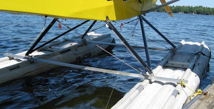
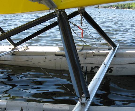
Of course since the joints can pivot,
side to side diagonal bracing is required.
With these brackets in mind and several sets
of floats to install, I realized an adjustable jig/fixture was in order. This
rig in the next picture enables me to set any float centre to centre width, any
fuselage height above the floats, any spreader bar position on the floats, any
cg position relative to step and any angle between float and fuselage. It uses
the fuselage landing gear sockets and four feet from the red S7 fuselage that is in the first picture
(It had an unfortunate death).
The top wood structure allows a plumb bob
to hang from a cg point; the bottom wood simulates the float step. The digital
level gets things lined up.
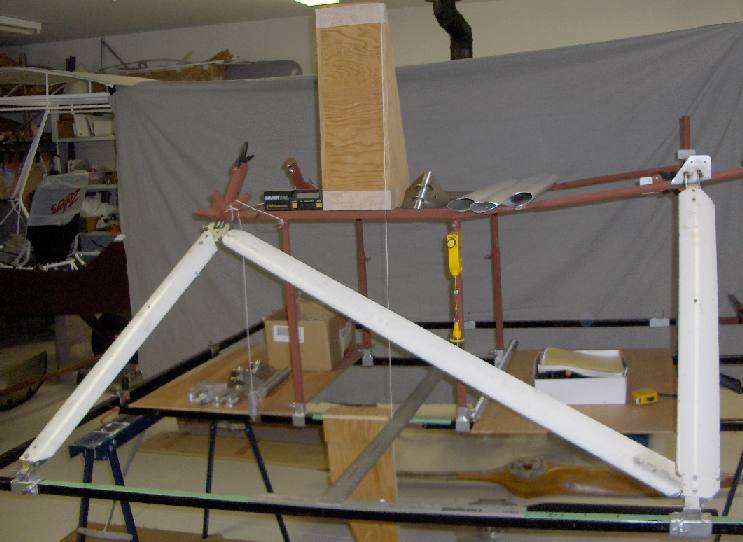
Once I’ve chosen a specific geometry I
can set the jig, bolt the strut end fittings in the jig and then cut and fit the
struts without going near the actual aircraft.
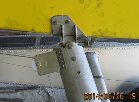
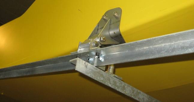
Here the fuselage stub gear and upper rear brackets are in place.
This is a new fixture used to tack weld
the tabs on that upper rear bracket which is done right on an actual fuselage.
The intent is to get both front and rear pivot bolts parallel to the aircraft
centre line in spite of the upward and inward tapering slope of the fuselage at
the rear bracket:
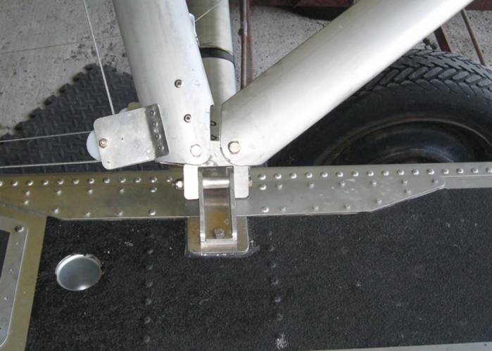
Here is the S7 on the Murphy 1500 floats
with rigging built using the jig and the fittings shown above. Float width is
80”; fuselage is 24” above float and level line is at 3.5 degrees to float.
Diagonal and aft struts are the temporary
telescoping steel tube.
Using the jig, the next set (LAS 1350)
were rigged in a day (again, with temporary, angle iron diagonal and rear
struts to confirm settings). I ended up
being quite happy with the strut length and did not need to adjust.
Here is the final set-up on the 1350
floats:
And a similar set on the 1500 Murphy
floats:
Full Lotus 1260’s on
S-7S
The last Lotus 1260s I
weighed were 197 lbs ready to bolt on. This set is only 173 and of that,
rigging was 40lbs (If you are interested CG is 5" fwd of the step. To do a
proper weight and balance you have to weigh the completed floats and calculate
the CG before installing them.
The V bottom on the 1500 makes for much smoother over the water runs on takeoff and touchdown. You can feel even a slight chop thru the Lotus flat bottoms just as you can with 1300’s above.
The 1500 gave an indicated 60mph (this is a low actual. I think GPS would have said 70 or more) at 4500 rpm (my economy cruise).
Since everyone says the Lotus being so blunt and bulky are slower, I was surprised to see a 65mph indicated at 4500. This is likely due to the bigger "flat plate area" of the larger 1500's compared to the 1260's.
The video will confirm but I feel that takeoff run is the same or even faster with the Lotus than the 1500's.
Again, the value of my float rigging jig came out. I'd cut and drilled all of the struts and fittings last fall on the jig. Before I took the 1500's off I made up all the diagonal brace cables and assembled everything on the Lotus away from the airplane. Then I raised the plane and switched floats.
The rigging is somewhat unique with streamline spreaders which have been machined with flats where they sit on the stiffener tubes and where brackets mount. The spreaders bolt to the stiffeners with stainless U bolts which also hold the strut fittings. Most parts are either aluminum or stainless.
These floats use some
recycled parts. The front and rear struts are off the Aerocets shown above; the
diagonals are from an early S7 rear lift struts. Most of the other fittings are
my design.
I got the
idea for that additional V brace at the front from a set a guy in
Lotus suggests the fore and
aft struts meet the float centered between the two stiffener tubes. This
results in them being in the way when walking fore and aft on the floats so I
like them closer to the inner stiffener tube. One disadvantage of this mounting
point is that on a hard touch down there is a bending moment on the spreader
bars tending to curve the mid point down. The tight diagonal braces add to this
bending force. The V brace resists this.
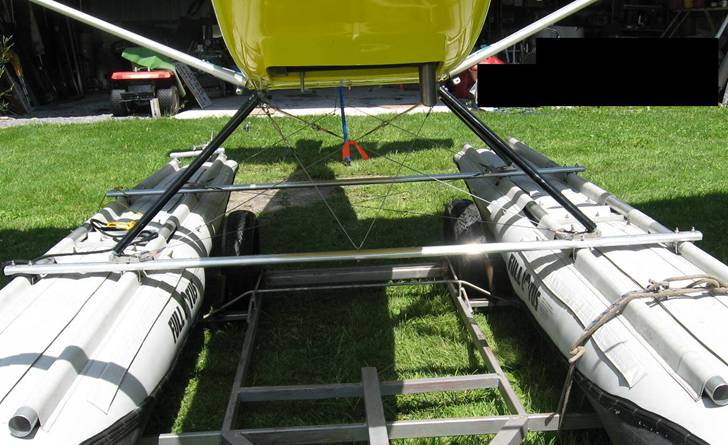
Here is another installation with V braces on 2” spreader tubes:
Steps above are 2” lengths of stiffener tube.
OK so for the horizontal diagonals which aren't quite so critical I used cheaper turn buckles.
Below the steps are on (formed from alum sheet 040 or 060?).
The plane is loaded
for the trip to the new owner NW of LaRonge
For some background on the geometry of
float mounting see: Geometry
Click for a short video
of a takeoff, or for some comments on float geometry
My email is peterc which is at pipcom dot
com. 705 877 8404
For sale:
Complete rigging packages for S7 to most
floats including Full Lotus using streamline tube spreaders.
Fuselage front and rear fittings and
struts for S7 that were on the Aerocet installation. Could easily be adapted to
other floats. Some clevises needed (Rans stock part)
LIFTING AN S-7
Traditionally lifting an airframe for
installing floats employed four eyes on the top of the cabin near the wing spar
attach points. A steel frame the size of the rectangle formed by the eyes
allowed stringing cables up to a central hook so that the plane was lifted more
or less horizontally.
This simplified keeping the fuselage
level for the float installation work.
On the S-7 it is straight forward to get
the two front points (see brackets below) and it may be possible to design
something to attach to the rear spar to fuselage fittings but because Rans tech
support people were uncomfortable with
this method I elected to use just the front spar points and the rear fuselage
lift handles. In this configuration the weight lifted at the tail is maybe 60
lbs and we have actually installed floats with the rear being held by a person.
See “movie shoot”.
I once used the firewall motor mounts as
a lifting point but I do not recommend this. Because it is further forward
there is much more weight on the tail and, even more important, the airframe is
less stable due to the lower lifting point on the aircraft so that if you let a
wing tip drop it doesn’t right itself.
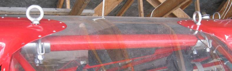
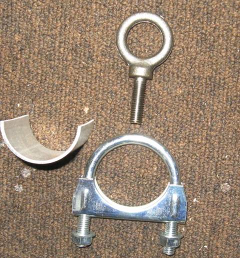
The lifting rings used here were made
from a 1 ¾” muffler clamp with one half of a long threaded rod nut welded to
the U, a 3/8” eye bolt and a sleeve from a piece of 2” x 1/8 wall aluminum pipe
to protect the spar carry thru and spread the load.
You can position
the U with the nut welded on roughly where it goes on the spar carry thru and
mark the windshield underneath. Then, with a long bit drill up thru the lexan
and cuff to get a starting point for grinding away an oval hole with a dremel
tool.
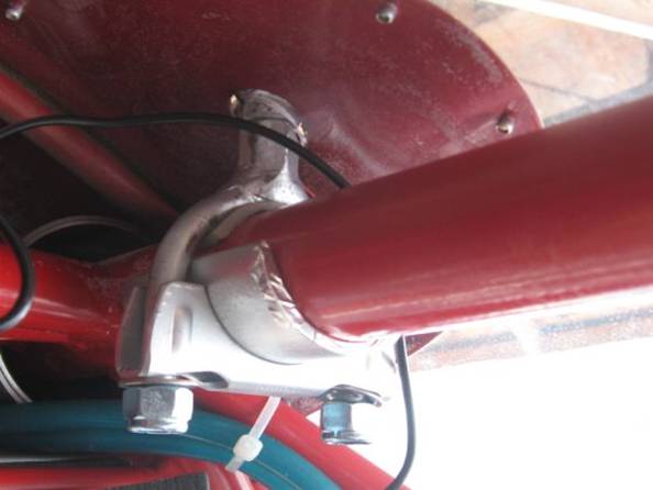
The eye bolts are
a little longer than required and can be shortened if you want. I leave the
rings on all year but they could be removed and a small cover put on the holes.
Not shown is a
two foot long steel bar with two eyes pointing down and one in the center
pointing up to hook onto the lifting cable which , in my case is a 12 volt
marine winch.
You must pull up vertically on
the fuselage eyes.
My
homebuilt 170 pictured above will also be for sale once the recover is
finished.